
Firstly select the required Revit Sheets or Revit Views to be exported from the Xporter main interface and then click the Export button from the ribbon.
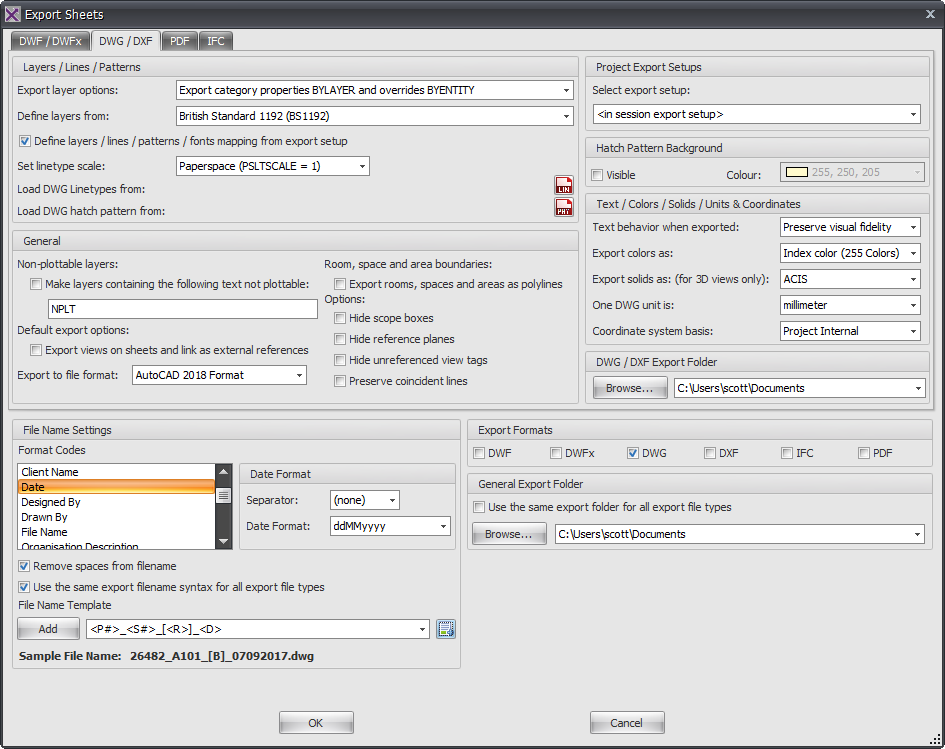
The top half of the Dialog box contain the specific settings and options for the resulting DWG / DXF files as shown by the below image.
- Export Layer Options – from the drop down there are three options from which to choose. Export Category properties BYLAYER and overrides BYENTITY, Export all properties BYLAYER, do not export overrides, Export all properties BYLAYER, create new layers for overrides.
- Load layers – select from the drop down one of the predefined layer export standards (American Institute of Architects, ISO standard 13567, Singapore Standard 83, British Standard 1192) or select your own company customized layer standard export file if preferred.
- Set Linetype Scale – select from the drop down the preferred option (Scaled linetype definitions, Modelspace (PSLTSCALE=0), Paperspace (PSLTSCALE = 1)).
- Load DWG Linetypes from – specify the default linetype file to be used for exporting (typically either acad.lin or acadiso.lin).
- Load DWG hatch pattern from – specify the default hatch pattern file to be used for exporting (typically either acad.pat or acadiso.pat).
- Text treatment during export – from the drop down choose how text formatting is handled when exporting from either Approximate (formatting will be maintained) or Extact (formatting will be lost).
- Export colours as – From the drop down select either Index colour or True Colour
- Export solids as – From the drop down select either ACIS Solids or Polymesh. These settings are relevant to 3D views only.
- One DWG unit is – From the drop down select the required unit of measure for exporting.
- Coordinate system basis – From the drop down select either Shared or Project Internal to determine the coordinate base system used for exporting.
- Non plotable layers – you can use non plotable layers if required when exporting by checking the box and then adding the ‘text’ contained in layer names to be excluded from plotting.
- Default Export options – Choose the required DWG export file format to be used (eg:2013, 2010 etc). If required views on sheets can be treated as Xrefs and linked when exporting by checking the box to Xref views on sheets and link as external references
- Room and area boundaries – these items can be exported as polylines if required by checking the box.
- Options – these items are optional when exporting if you want to hide scope boxes, reference planes, and unreferenced view tags.
- If you want exported DWG files to be placed in their own folder separate from other export types then click the ‘Browse’ button and specify the export folder location. Note that this browse button will be greyed out and unavailable if using the General Export Folder option below.
The lower portion of the Dialog box determines the File naming, export location and file format settings for the exported files as shown by below example.
- The File Name Settings panel – provide the means to determine your file naming convention. Use the Format codes list to create the desired combination for the file name template (a sample preview is given as a guide). Use the date format options to select the required date format and date separator.
- Export Formats Panel – is where you select the required output formats by checking the required boxes
- General Export Folder – can be selected if you want to export all your various export formats to the same location by ticking the box and selecting the export folder. If you prefer to export each different file type to a separate folder then leave this box un-ticked and use the alternative DWF export folder above instead.
Category: Xporter